Friday, December 13, 2013

Sketching- Multi-Views

Introduction
It’s a very common occurrence to see a product advertisement and think, “I thought of an idea for something like that just a few months ago.” People spend a lot of time in their various interest areas and envision ideas for making things work better.Spend some time with someone who has a permanent disability and see how many product ideas come to mind that would provide a degree of freedom to a person whohas lost a physical capability. Coming up with wonderful ideas are only the first step in developing solutions to problems. At some point, ideas must be built.

You’ve practiced different techniques for sketching objects so that they appear to have a three-dimensional quality. These techniques are excellent for quickly communicating ideas to both technical and non-technical people. Those who make their living building ideas require a different type of drawing format. A multi-view sketch, also referred to as an orthographic projection sketch, is the standard sketch format used by engineers to communicate ideas to professionals in the building trades.

However, pictorials do not provide accurate information about the true size and shape of an object and all of its features. It is often the case that engineered objects have features and edges that are obscured by the standard surface views of a multi-view drawing. These views require hidden linesWhen engineers create drawings of cylindrical objects, or objects that have holes, they must represent their axes and axes points with centerlines.

Knowing how to sketch and interpret multi-views is an important skill for any engineer. In this activity, you will develop your ability to see and sketch objects as a series of related two-dimensional views. Understanding and using the different line conventions, discussed earlier in this lesson, will help when creating these views.

Equipment
Pencil
Engineering notebook

Procedure
Study the images below. The various surfaces of the object are identified by letters on the isometric drawing and by numbers on the multi-view drawing. In the table, write the number that corresponds with the lettered surface in each of the top, front, and right side views.


Sketching- Perspective

Introduction
If you can stand on a straight road and look down the road, it appears as if the sides of the road eventually narrow to one point. The center of the road vanishes when the road meets the horizon. If the road is straight enough and long enough, the sides of the road not only look like they are converging to a single point, but the road seems to appear to vanish as it meets the horizon. A similar effect occurs if you stare upward from the base of a tall building. The vertical edges of the building will appear to angle in toward each other. This effect is called perspective.

The human eye sees the world in perspective. Objects that are further away from the eye appear smaller, and edges appear to recede into the distance. Perspective sketches depict objects in much the same way that the human eye sees the world.

There are three different types of perspective drawings: one-point, two-point, andthree-point perspective. The different types of sketches are frequently used by architects, industrial designers, and illustrators when representing large scale objects or environments in which the effect of distance must be taken into consideration.

In this activity, you will practice your sketching skills by generating perspective views based on provided isometric views of objects. You will also apply your skills by creating one-point and two-point perspective of other imagined or real objects that you choose.

Equipment
Grid paper or engineering notebook
Pencil and/or pen
Puzzle cube puzzle pieces
Various objects

Procedure
Study the object represented in the isometric views below. Use the vanishing point and horizon line indicated to lay out light construction lines and create a one-point perspective sketch of the object within the given box. The perspective sketch must show the object in a top, left side, front view orientation. Delineate the visible edges of the sketch with heavy object linesDO NOT ERASE YOUR CONSTRUCTION LINES. Add tonal shading to the sketch when finished.


Sketching- Isometrics

Introduction
How do reading the face of a clock and sketching isometric pictorials relate to each other? Picture a cube in your mind. All of the surfaces of the cube form right angles with their adjacent faces. If you were to draw an isometric pictorial of the cube, you would see that the edges point toward 2 and 8 o’clock, 4 and 10 o’clock, and 6 and12 o’clock. This idea helps when sketching isometric pictorials on writing surfaces that do not have isometric grids.

Isometrics are a common pictorial used both for concept sketches and to represent designs in technical drawings.

Equipment
Pencil
Isometric grid paper
Orthographic grid paper, graph paper, or engineering notebook

Procedure
In this activity, you will develop your isometric sketching skills by first drawing isometric views of objects that are already given in an isometric orientation. You will apply your sketching skills in later exercises to sketch orthographic views of objects that are not given in isometric orientation and to represent your ideas and designs.

When referring to the orientation of an isometric view, the isometric view is labeled in the order of first face, second face, then third face.  For example, the image on the left below shows a top, front, right side view isometric. The same object is pictured again on the right but is shown in a top, left side, front view orientation. We will almost exclusively use the top, front, right side view in this course. In fact, the orientation of the isometric will dictate how you label and show the orthographic projections (or side views) of the object in later activities.


Wednesday, December 11, 2013

IED Activity 4.1- Puzzle Cube Design Challenge

Introduction
Have you ever looked at a product that has been well-designed? Do you find yourself asking questions such as, “How did the designer think of that idea?” or “What is involved in the creation of that product?” The more you study and learn about design and how designers create items, you begin to learn certain skills and knowledge that you can only acquire through experience. Design challenges provide opportunities to apply skills and knowledge in unique and creative ways.

Taking an idea you have and transferring it from a concept to a sketch, to working drawings, to models, and then to a working prototype is exciting and fun. It also entails several steps. When you are a one-person design and build team, the task of effective communication is rather simple. However, what happens when you must communicate your ideas to others, or when the responsibility for building a team’s solution falls on someone else’s shoulders? This increases the level of responsibility significantly and requires the development of a complete set of design documentation in order to communicate effectively.

This project will provide you the opportunity to exercise your creativity and develop your sketching and modeling skills, as well as your ability to use the computer as an efficient communication tool.

Equipment
Engineering notebook
Pencil
27 – ¾ in. hardwood cubes
27 – interlocking plastic centimeter cubes (optional)
Paper towels
Isometric grid paper
Orthographic grid paper
Markers (colored pencils or paint are optional)
Wood glue
Sandwich-sized Ziploc® bag for storage
220 abrasive paper
Computer with 3D CAD solid modeling software

_____________________________________________

STEP 1: -Define problem (including a design brief)


STEP 2: Generating Concepts
               -Brainstorming (including part possibility configurations)
               -Research (including applied statistical analysis)


STEP 3: Develop a Solution
               -Explore possibilities (develop two different puzzle cube possibilities, and use isometric drawings, sketch out all three levels of cube)
               -Developing a design proposal (create a multi-view drawing for each piece of the chosen cube [including an isometric sketch])


STEP 4: Construct and Test a Prototype
               -Physical prototype 
               -Prototype packaging 
               -Virtual prototype (see step 6)


STEP 5: Evaluate Solutions
              -Test, evaluate, and redesign (answer the following questions: Why is it important to model an idea before making a final prototype? Which assembly constraint(s) did you use to constrain the parts of the puzzle to the assembly such that it did not move? Describe each of the constraint types used and explain the degrees of freedom that are removed when each is exhibited.


STEP 6: Present Solution (include drawing files created on Autodesk Inventor). Include:
             1.Title Page
             2.Parts List/Exploded View
             3.Assembly Page
             4.Individual Parts Page (All 5 Pieces)


IED Design Challenge- Paper tower

Goal of Challenge:
   -Create the tallest tower that can hold a tennis ball and can withstand the highest level of wind

Limitations:
   -Must be at least 18" (from bottom of ball to surface of table)
   -Must hold up against wind for at least 10 seconds (Ball cannot fall, tower cannot tip)
   -Must use only designated materials
   -Tower must be FREE STANDING (cannot be fastened to table by any means [ex. Tape])

Materials: 
     •1 school newspaper
     •3 pieces of computer paper
     •2 pieces of cardstock
     •2 feet of masking tape
     •5 rubber bands
     •1 tennis ball (cannot be modified)
     •1 pair of scissors (for use during construction only, cannot be used in actual structure)
     •1 ruler/scale (for use during construction only, cannot be used in actual structure)


     Above are steps 1-6 of the design process, applied to this activity.


IED Activity 1.8: Paper Bridge (Instant Challenge)


Introduction

Solving a problem is an amazingly creative process. Creativity can be messy. However, creativity can be channeled into a meaningful solution by using a structured design process. In this activity your team will design a solution to a problem using an engineering design process. You will document the process in your engineering notebook.


Equipment
·         Engineering notebook
·         Pencil
·         ¾ in. wooden blocks (2)
·         1 sheet of 8 ½ x 11 in. cardstock
·         Assorted construction tools such as scissors


Procedure
1.    Follow the direction of the teacher while completing this activity.
2.    Use the design process learned earlier in this lesson. Document each step in your engineering notebook. 
3.    Design and build a product that maximizes the distance between two blocks which are connected by a continuous route of paper. The product must meet the constraints below.
a.    The paper must form a continuous chain of connectivity from one block to another without touching the tabletop.
b.    Paper-to-paper linkage will be considered continuous.
c.    The two wooden blocks are ¾ in. wooden blocks.
d.    Both blocks are at table height.
e.    Card stock can be modified.
f.     Additional material can be used during construction, but not on the final product.
4.    The winning design meets the constraints above with the blocks farthest apart.


IED Activity 1.4: Product Improvement


Introduction
Hummers®, iPods®, cell phones, clothes, and video games are just a few products that are familiar to most people. What is it about any of these products that you like? What causes you to want to buy a cell phone or an IPod? Is it the commercials or the appearance of the product? Whatever the reason, design plays a vital role in the creation and marketing of any product.


Equipment
·         Paper
·         Plain white coffee cup (1 per class) OR alternate consumer product
·         Pencil


Procedure


This activity is designed to provide an introduction to design. As a team of two, you will brainstorm ways to enhance or change a plain white beverage container so that nearly every consumer would want to purchase it. Remember to apply the rules for brainstorming that were identified in the PowerPoint during this activity. The following list is available to guide your team through this activity:
·         Assign a recorder and a speaker for your group.
·         Brainstorm for five minutes with your team to identify enhancements or changes that you would make to the item. The recorder will make a list of all ideas mentioned in those five minutes. Changes or enhancements could be anything; you are not limited by cost.
·         After five minutes, select ideas to enhance or change the item from the brainstorming list.
·         For the next ten minutes, each member of the team should develop and sketch a potential change or enhancement to your product.
·         Your team will take five additional minutes to develop a justification for each potential change to the item.
·         Your team speaker will present your changes to the class.


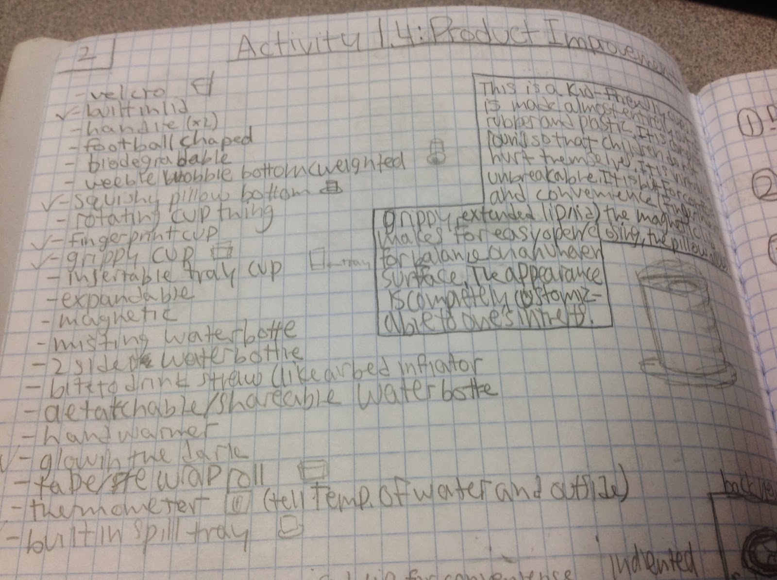
     Located above is an image snapped out of my engineering journal. The list on the left side is a list that I and my partner, Sarah, brainstormed. It was a list of problems we both thought constantly occurred with everyday cups/water bottles that should be remedied immediately.
     On the right is merely a paragraph in a box summing up generally what our cup/water bottle would be about (including details on what made it different from other cups/water bottles).

     Located below is a sketch of what our cup/water bottle would look like, if we had the time and resourses to create a prototype. The larger view on the left is a zoomed out view of the whole cup/water bottle, along with annotations for the additional functions. in the upper left, there is a smaller sketch of what the back view would look like and the three boxes in the bottom left are of the specialized lid of the cup/water bottle and what alterations we made to it.